HC-06 Bluetooth Module
Bluetooth is a wireless technology standard for exchanging data over short distances (using short-wavelength UHF radio waves in the ISM band from 2.4 to 2.485 GHz) from fixed and mobile devices, and building personal area networks (PANs). Range is approximately 10 Meters (30 feet).
The HC-06 is a class 2 slave Bluetooth module designed for transparent wireless serial communication. Once it is paired to a master Bluetooth device such as PC, smart phones and tablet, its operation becomes transparent to the user. All data received through the serial input is immediately transmitted over the air. When the module receives wireless data, it is sent out through the serial interface exactly at it is received. No user code specific to the Bluetooth module is needed at all in the user microcontroller program.
How it works

The module has two modes of operation, Command Mode where we can send AT commands to it and Data Mode where it transmits and receives data to and from another Bluetooth module. By default the device was in Command mode and needs to pair with some device to get it into data mode.
FEATURES:
- Bluetooth v2.0+EDR1
2.4GHz ISM band frequency
Default baudrate: 9600
Power supply: 3.6V to 6V DC
Passkey: 1234
Board needs 4-lines to communicate most of the times, Vcc, Gnd, RX and TX pin. There are two additional pin onboard, one is STATE pin and the other is EN pin, this Reset pin can be used to send reset signal from microcontroller to reset the bluetooth.

HC-06 works on serial communication. The Android app is designed to send serial data to the Arduino Bluetooth module when a button is pressed on the app. The Arduino Bluetooth module at other end receives the data and sends it to the Arduino through the TX pin of the Bluetooth module(connected to RX pin of Arduino). The code uploaded to the Arduino checks the received data and compares it.
Building Circuit
-
VCC – To supply +5V
GND – To make it Ground
TXD – Data TX pin
RXD – Data Rx Pin

After connecting the Arduino with the Bluetooth HS-06 and LED, we start writing the code.

First of all, we need to install the Bluetooth Terminal app on the smartphone.

Pair your phone with HC-06. for doing this go to Settings->Bluetooth->Scan device->select HC-06 and pair it. Pass code to pair is ‘1234’.
Open Bluetooth Terminal software, go to options and select ‘connect a device – secure’ option. It ask for pass code enter 1234.
If you send ‘1’ it will make to LED (Connected on pen-13) ON and if you send ‘2’ it will make the LED OFF. The Arduino code also sends the current state of LED also. If you send ‘?’ it will send the instruction.
This is the code file:
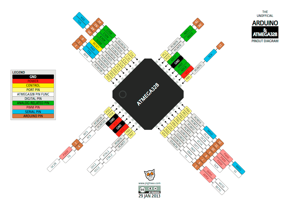
I designed my board with an Atmega 328p processor using Eagle software.

After producing the board, as we did in the previous week of electrical production.

ATmega328_Pinout I'll use it to help me connect the pieces I want to work on.
I used the rgb bluetooth android app.
i2c programming master transmitter slave receiver
The Inter-Integrated Circuit (I2C) Protocol is a protocol intended to allow multiple "peripheral" digital integrated circuits ("chips") to communicate with one or more "controller" chips. Like the Serial Peripheral Interface (SPI), it is only intended for short distance communications within a single device. Like Asynchronous Serial Interfaces (such as RS-232 or UARTs), it only requires two signal wires to exchange information.
I am going to use the I2C protocol with master writer/slave receiver configuration.
I2C communication protocol, you have two devices, a master and a slave, which are interconnected by two lines, a data line and a clock line.In Arduino Uno, the data line is Analog pin 4(A4) and clock line is Analog pin 5(A5). This however is different for different for different boards.
When the clock pin goes from low to high, one bit of data is transferred via the data pin.The slave board may then either send back data via the same data pin or perform a task(as in our case). The first eight bits, however, are reserved for the address of the slave Arduino board to which the master sends values.
I use analog read in the master Arduino board, to get the value of a potentiometer connected to it. Then this value is transferred to the slave Arduino Board and if it is above a threshold, the LED connected to the slave Arduino lights up.
An I2C bus has two signals, along with a power and ground connection.
The two signal lines are as follows:
SDA – This is the bidirectional data line.
SCL – This is the clock signal.

Slave devices do have an address, and this address needs to be unique on the bus. They use a 7-bit addressing scheme, so up to 128 slaves can be on one I2C bus.
SDA and SCL connections for I2C between Arduino. I am about to try two Arduino Unos A4 and A5 that we will combine two Arduinos together and exchange data between them. One of them will be the master, and the other will be the slave.
Here is how I connected my two Arduino Unos together:

The sketch for the master side of this experiment is very simple, in some ways the I2C side is even simpler than the one used in the first demonstration. This is because we are just sending data to the slave and are not expecting to get any back.
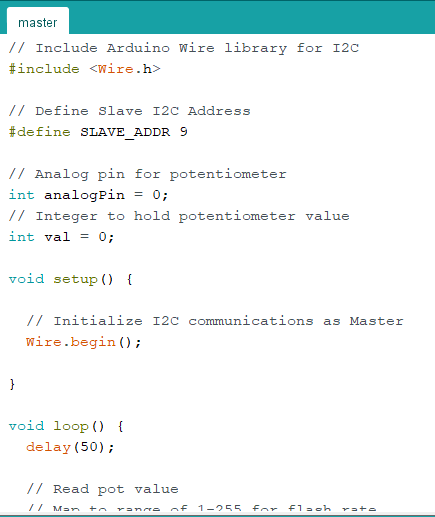

with all I2C sketches, we start by including the Wire library.
Master code is simple. This is because we are only sending the data to the slave and we don't expect any to be recovered.
Because we're using a potentiometer, we'll need to define both the pin connected to it and a variable to hold its value.
All we do in setup is initialize the I2C connection as master.
We read the potentiometer value and set it to a range of 01-255.
Turning the potentiometer should now vary the LED blink rate on the slave.
This is the site for group assignments:Press here
This is the code file:
This is the Apk file:
This is the Master file:
This is the Slave file: